Product introduction
NAEFH Simulator Transformer Test Equipment specilized for testing PT, CT error and the impedance, admittance test. Meet national JJG313-94 "Measuring Current Transformer test procedures" and JJG314-94 "Measuring voltage transformer test procedures" requirements.
Also called name
Transformer calibrator, transformer test equipment,NAEFH Automatic Simulator Transformer Test Equipment
The Characteristics of the products
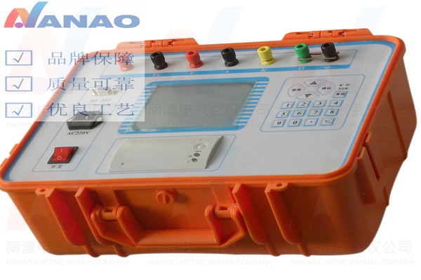
1, Uses 320 x 240 dot matrix LCD, visible range, with a long-life backlight, easy to use
2, Entire English operation interface, attractive interface
3, Dial indicator, ratio difference, angle difference using large font display, easy to observation
4, Company's simulation-type transformer field calibrator fully meet JJG314-1993 and JJG314-1994 requirements, automatic sampling
5, Automatically determine the polarity of the error, the error ratio
6, PC software with virtual instruments open function7, S-Class solve measurement problem
8, Automatic switching range
9, Using unique circuitry and advanced DSP technology combine to completely remove the RC phase shifter circuit instability
10, Power consumption: <15VA (without micro-printer); <25VA (with micro-printer)
11, Harmonic rejection ratio:> 40db
12, Dimensions (L × W × H): 260 × 350 × 150mm3
13, Weight: 6kg
The parameters of the products
1 , Working environment
1 ) Temperature : 5 ℃ ~ 40 ℃; Relative humidity : <80% (25 ℃ when )
Altitude : <2500m
Power frequency : 50Hz ± 0.5Hz; Supply voltage : 220V ± 5V
2 ) Measuring range:
Phase component ( % ) : 0.0001 ~ 200.0 ; Resolution : 0.0001
Quadrature component ( stars ) : 0.001 ~ 700.0 ; resolution: 0.001
Impedance (Ω): 0.0001 ~ 20.0; Resolution : 0.0001
Admittance (ms): 0.0001 ~ 20.0; resolution: 0.0001
3 ) Basic error:
Phase component : ΔX = ± (X × 2% + Y × 2%) ± Dx ( with an optional )
Orthogonal components : ΔY = ± (X × 2% + Y × 2%) ± Dy ( with an optional )
"X", "Y" - the instrument display
"Dx, Dy" - the quantization error of the instrument
Dx = 2, Dy = 5
4 ) dial indicator : level 2 ( level 1 available )
2, Scope of work:
1 ) Current : (1% ~ 149%) In (In = 5A)
(5% ~ 149%) In (In = 1A)
2 ) Voltage : (5% ~ 149%) Un (Un = 100V, 150V, 100V /)
(5% ~ 149%) Un (Un = 100V / 3)
3, Working load:
1 ) Current : TO right TX <0.12Ω cosΦ = 1
2 ) Voltage : a pair of x <0.25VA (100V)
4 , Wrong polarity indication
When the operating current ( voltage ) reaches the rated current ( voltage ) of more than 5% error for more than 180 %, the proper polarity indication .
Note: If greater than the rated operating current ( voltage ) more than 10% , should not appear polarity indication , there is a fault , please do not increase the current( Voltage ) , so not to start the instrument .
5 , Ratio error indication :
When the operating current ( voltage ) reaches the rated current ( voltage ) of more than 5% error of more than 30% but less than 180% , the proper ratio error indication.
6 , Insulation and pressure test and description:
Terminal (TX) terminals connected
Power outlet on the casing can withstand 1.5kV, 1 minute pressure