有限公司")
 冲击电压发生器/冲击电流发生器
NAICH多分量波形全自动雷电冲击电流发生器试验装置
NAICH multi-component waveform automatic lightning impulse current generator test device
产品别名
多分量波形冲击电流试验装置,四分量波形冲击电流装置,4分量波形冲击电流试验,D分量波形冲击电流装置,多分量冲击电流试验,四分量雷电冲击电流,分量波形冲击电流试验,分量波形冲击电流发生器装置,多分量雷电冲击电流,多分量波形雷电冲击,四分量冲击电流发生器,分量雷电冲击电流,分量波雷电冲击,多分量冲击电流试验装置,分量波形雷电冲击,D分量波冲击发生器
设备概述
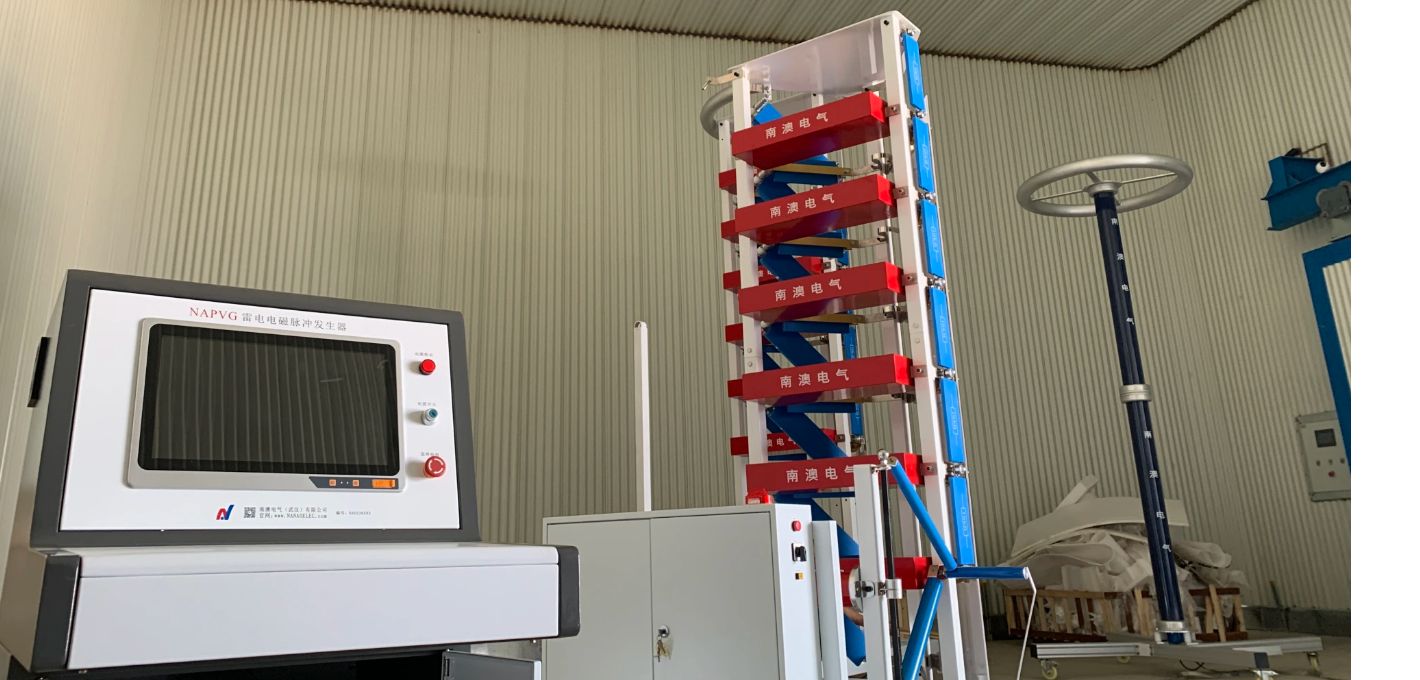
本套多分量波形全自动雷电冲击电流发生器试验装置,可用于飞机整机、飞机局部舱段或发动机组件的雷电防护测试,确定飞机电气系统线缆上的实际感应电平及瞬态波形,确定或验证雷电防护相关的瞬态控制电平和设备瞬态设计电平。发生器也可用于燃油系统的非电气系统导体(如控制线缆、燃油、液压、气压管路以及结构件)或系统效应的测试。
本系统输出D分量峰值100kA,T1≤30µS,T2≦500µS(指数波形或震荡波形)。
依据标准
GB 18802.1-2011 低压配电系统的电涌保护器(SPD):性能要求和试验方法
GB/T 18802.12-2011 低压配电系统的电涌保护器(SPD):选择和使用导则
IEC 61643-1-2011 Low-voltage surge protective devices –Part 1:Surge protective devices connected to low-voltage power distribution systems –Requirements and tests
IEC61643-12-2011低压浪涌保护装置:连接到低压配电系统的电涌保护装置.选择和应用原理
UL1449-2015 Surge protective devices
f) YD/T 1235.1-2002通讯局(站)低压配电系统用电涌保护器技术要求
g) YD/T 1235.2-2002 通讯局(站)低压配电系统用电涌保护器测试方法
h) GB/T 16927.1-1997高电压试验技术 一般试验要求
i) GB/T 16927.2-1997高电压试验技术 测量系统
j) YD/T 5098-2001通信局(站)雷电过电压保护工程设计规范
k) GB3567-99 飞机雷电防护鉴定试验方法
l) GB/T 17626.5-2018 电磁兼容 试验和测量技术 浪涌(冲击)抗扰度试验
主要参数
输入电源:交流,50Hz/60Hz
变压器:油浸式单相,380V/70kV/10kVA,
充电电压:DC80kV,充电电流0.1A
充电极性:正负极性可自动变化
充电时间:输出100kA电流每60s充放电一次,
结构型式:多台扇形布置,可单独放电,也可联合放电。
冲击电容器: 10台冲击电容器
高压油浸电容器参数:80kV/2µF
单台冲击总能量:6.4kJ
单台冲击总能量:64kJ
电容器寿命:正常工况下,设备额定充放电次数超过20万次,80%额定电压下,可长期使用。额定输出运行时,预留余量大于10%。
主要组成部件
本体扇形结构
本体电容器采用扇形结构,电容器垂直放置, 底部连接固定;
本体电容器采用扇形向心对称结构,从结构上确保每组电容器距离放电间隙距离相同,很好地保证放电电流的均匀性。在长期使用中这样的结构设计可以保证电容器使用寿命均匀,从而延长了设备寿命。
电容器可以单组运行,也可以并联运行,手动换接电路比较方便。每组电容器放电过程中均串联电阻,能够保证电容器安全运行。
NAICH Multi-component Waveform Automatic Lightning Impulse Current Generator Test Device
Also Called Name
Multi-component waveform impulse current test device, four-component waveform impulse current device, 4-component waveform impulse current test, D-component waveform impulse current device, multi-component impulse current test, four-component lightning impulse current, component waveform impulse current test, component waveform impulse Current generator device, multi-component lightning impulse current, four-component impulse current generator, component lightning impulse current, component wave lightning impulse, multi-component impulse current test device, component waveform lightning impulse, D-component wave impulse generator
Equipment Overview
This set of multi-component waveform automatic lightning impulse current generator test device can be used for the lightning protection test of the aircraft, the aircraft's partial cabins or the engine components, and determine the actual induction level and transient waveforms on the aircraft electrical system cables. Determine or verify the transient control level and equipment transient design level related to lightning protection. The generator can also be used to test the non-electrical system conductors of the fuel system (such as control cables, fuel, hydraulic, pneumatic lines and structural parts) or system effects.
The system output D component peak value 100kA, T1≤30μS, T2≤500μS (exponential waveform or oscillating waveform).
According Standards
a) GB 18802.1-2011
b) GB/T 18802.12-2011
c) IEC 61643-1-2011 Low-voltage surge protective devices –Part 1:Surge protective devices connected to low-voltage power distribution systems –Requirements and tests
d) IEC61643-12-2011
e) UL1449-2015 Surge protective devices
f) YD/T 1235.1-2002
g) YD/T 1235.2-2002
h) GB/T 16927.1-1997
i) GB/T 16927.2-1997
j) YD/T 5098-2001
k) GB3567-99
l) GB/T 17626.5-2018
Main Data
Input power: AC, 50Hz/60Hz
Transformer: oil-immersed single-phase, 380V/70kV/10kVA,
Charging voltage: DC80kV, maximum charging current 0.1A
Charging polarity: positive and negative polarity can be changed automatically
Charging time: output 100kA current to charge and discharge once every 60s,
Structure type: Multiple units are arranged in a sector, which can be discharged individually or in combination.
Impact capacitor: 10 impact capacitors
Parameters of high-voltage oil-immersed capacitors: 80kV/2µF
Total impact energy of a single unit: 6.4kJ
Total impact energy of a single unit: 64kJ
Capacitor life: Under normal operating conditions, the rated charge and discharge times of the equipment exceed 200,000 times, and it can be used for a long time under 80% of the rated voltage. When the rated output is running, the reserve margin is greater than 10%.
Main Components
Body Sector Structure
The body capacitor adopts a sector structure, capacitor is placed vertically, and bottom is connected and fixed;
The body capacitor adopts a fan-shaped centripetal symmetrical structure to ensure that each group of capacitors is at the same distance from the discharge gap to ensure the uniformity of the discharge current to the greatest extent. In long-term use, such a structural design can ensure the uniform life of the capacitor, thereby prolonging the life of the device.
Capacitors can be operated in a single group or in parallel, and it is more convenient to switch the circuit manually. Each group of capacitors are connected in series with resistors during the discharge process, which can ensure the safe operation of the capacitors.
南澳电气武汉公司 版权所有 NANAO ELECTRIC. Copyright © 2004-2018, www.HipotHV.com All Right Reserved. 备案号:鄂ICP备16008747号-2
服务热线